Dextrous Robotic Manipulator Project
Project Objectives
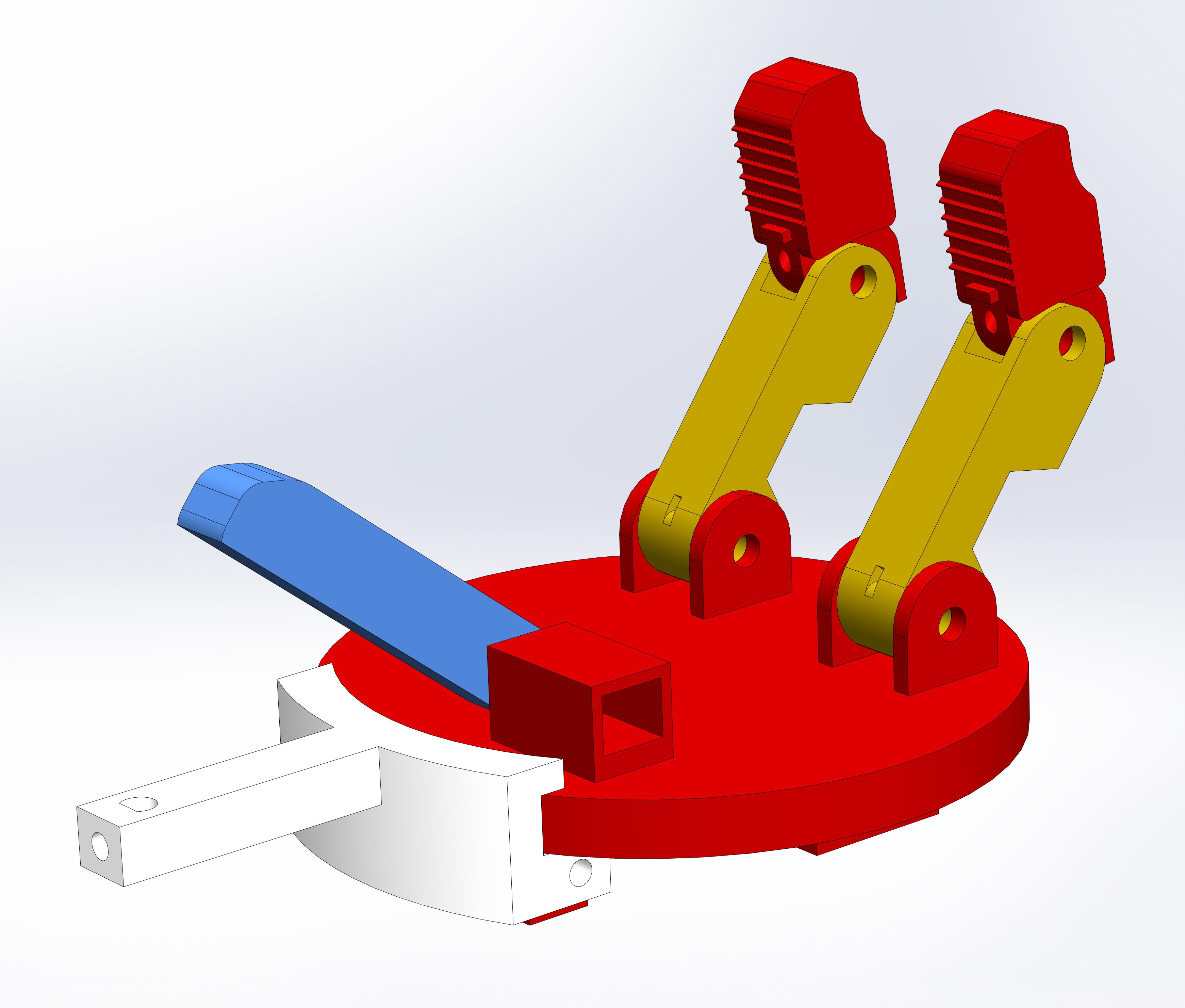
This project page details my work in the design and creation of a dextrous grasping hand. Using an underactuated finger design inspired by the Yale OpenHand Project, the goal of this project was for the designed hand to be able to grasp and lift a variety of objects without manual control.

The hand design shown above consists of two underactuated fingers and a fully actuated thumb, controlled by micro-gearmotors. I selected the motors to fit the necessary torque requirements so that the hand could lift the objects it was required to, from a box of paperclips to a plastic trophy. The hand is affectionately named EVE, the Electromechanical Versatile End-effector to pair with the controls framework called ADeMM, the Adjustable Dextrous Manipulator Model. This naming choice was inspired by art, specifically from Michaelangelo's "The Creation of Adam", due to the emphasis on the hand and that I believe aesthetics and artistry can be very important in engineering, especially when creating a product.
Project Outcomes
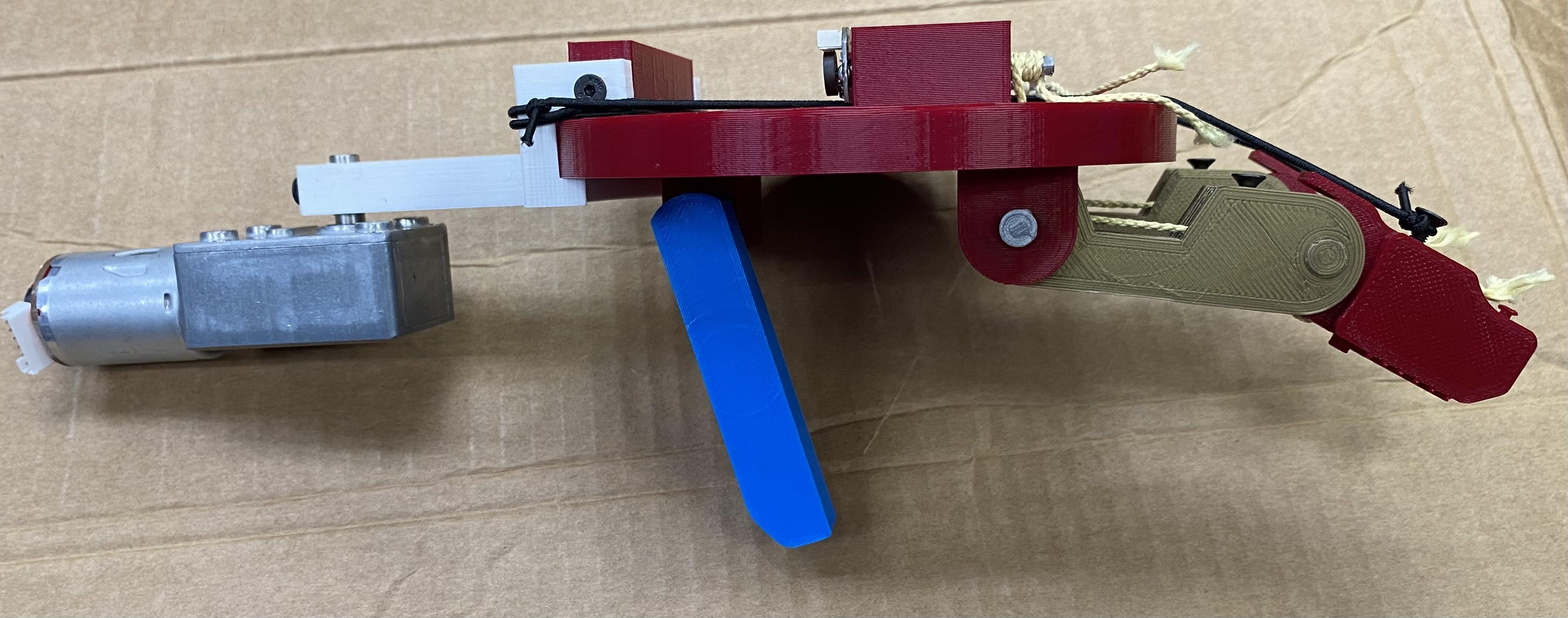
The outcome of this project was that the hand was able to lift one of the objects, the box of paperclips, and place it back down. My contributions to this project where in designing the hand and assembling it, creating the controls model for the hand using linearization and pole placement to make the hand perform in a stable and linear manner. I also designed the circuits required so that the signal the hand received from the flex sensors was steady and output over the whole voltage range that can be ready by Teensy boards.

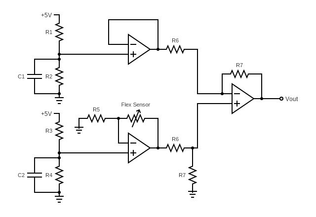
Shown above is the hand created for the final version of this project, during the testing and validation project stage.The two underactuated fingers both have notches where the flex sensors were attached (not pictured) so the position of the fingers can be tracked during use and controlled for compliance. The flex sensors were difficult to work though, and the output of the resistive circuit they were used in would reach the maximum voltage possible with very little bending. To counteract this, the circuit shown below was designed, which cen be divided into three op-amp subcomponents. The bottom left op-amp is the resistive circuit that outputs a voltage based around how much the flex sensor was bent, (and therefore the resistance it created). The top left op-amp is a unity gain buffer designed to produce a reference voltage for the flex sensor circuit, so that the reference voltage is equal to the minimum voltage output by the sensor circuit. These two op-amp circuits feed into the op-amp on the right, which acts as a difference amplifier between the two op-amps on the left. The complete effect of these three op-amps is that the voltage output by the finger sensors would be 0V when the fingers (and flex sensors) where straight, and 3.3V when the fingers where completely bent, giving a linear voltage output over the total usable voltage range to measure the finger position.

Technical Skills required
The technical details required in the completion of this project represent the many facets of mechanical engineering, both in the design and implementation stages. In the design of this project I needed to possess CAD design proficiency and knowledge of GD&T, to ensure that the parts of the hand would fit together and move in the way intended. Knowledge of additive manufacturing was also required here, so that I could properly design the PLA components. I also utilized industry practices in motor sizing to make sure that the selected gear motors would be enough to lift the required loads. In the implementation phase of this project I had to use my skills in control design and hardware design to make sure that the fingers behaved properly and responed as intended.